
Electric motors are the backbone of industry. More than 300 million motors are used in industry, large buildings and in infrastructure globally, and 30 million new electric motors are sold each year for industrial purposes alone. The fact that these motors use approximately 29 percent of overall global, and 69% percent of industrial electricity consumption indicates their importance (1)
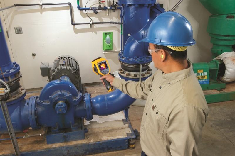
Infrared Cameras are very useful for both troubleshooting motor problems as well as for condition monitoring, for long-term preventive maintenance. Using a handheld infrared camera, you can capture infrared temperature measurements of a motor’s temperature profile as a two-dimensional image.
Fluke infrared cameras include IR-Fusion*, a technology that fuses a visual, or visible light, image with an infrared image for better identification, analysis and image management.
* Get four times the pixel data with SuperResolution, which captures multiple images and combines them to create a 640 x 480 image (Ti450/PRO, TiX560 and TiX520) or a 1280 x 960 image (TiX580 and Ti480/PRO); then transfer them to the included Fluke SmartView software to reveal 3,145,728 pixels and see infrared in a whole new way.
Infrared cameras of electric motors reveal their surface temperature, a key component of their operating condition. Such condition monitoring is important as a way to avert many unexpected motor malfunctions in systems that are critical to manufacturing, commercial and institutional processes. Such preventive actions are important because when a critical system fails, it inevitably increases costs, requires the reallocation of workers and material, reduces productivity and, if not corrected, can threaten corporate profitability and, possibly, the wellbeing of employees, customers and/or clients.
What to check?
Ideally, you should check motors when they are running under normal operating conditions. Unlike an infrared thermometer that only captures temperature at a single point, an infrared camera can capture temperatures at thousands of points at once, for all of the critical components: the motor, shaft coupling, motor and shaft bearings, and the gearbox. Remember: each motor is designed to operate at a specific internal temperature; the other components should not be as hot as the motor housing.
What to look for?
All motors should list the normal operating temperature on the nameplate. While the infrared camera can not see the inside of the motor, the exterior surface temperature is an indicator of the internal temperature. As the motor gets hotter inside, it also gets hotter outside. Thus, an experienced thermographer who is also knowledgeable about motors can use infrared imaging to identify conditions such as inadequate airflow, impending bearing failure, shaft coupling problems, and insulation degradation in the rotor or stator in a motor.
In general, it is a good idea to create a regular inspection route that includes all critical motor/ drive combinations. Then, save an infrared image of each one on a electronic device and track measurements over time. That way, you’ll have baseline images to compare to, that will help you determine whether a hotspot is unusual or not, and, following repairs, to help you verify if the repairs were successful.
What represents a “red alert?”
Equipment conditions that pose a safety risk should take the highest repair priority. After that, consider that each motor has a maximum operating temperature that usually appears on its nameplate and represents the maximum allowable rise in temperature of the motor above ambient. (Most motors are designed to operate in ambient temperatures that do not exceed 40 °C.) Generally speaking, each 10 °C rise above its rated temperature cuts a motor’s life in half. Regularly scheduled infrared inspections of electric motors identify motors which are starting to overheat. Even an initial infrared image will reveal whether a motor is running hotter than a similar motor doing a similar job.
What’s the potential cost of failure?
For a specific motor, you could do an analysis based on the cost of the motor, the average amount of time a line is down from a motor failure, the labour required to change out a motor, etc.
Of course, productivity losses from downtime vary from industry to industry. For example, lost production from a papermaking machine can be as much as $3,000 per hour while in the steel casting industry losses can be as high as $1,000 per minute.
Follow-up actions
If you suspect overheating is the result of one of the following, consider the action described:
a. Inadequate airflow. If a brief shutdown is possible without affecting the plant process, shut off the motor long enough to perform minor cleaning on the air intake grills. Schedule a thorough motor cleaning during the next planned plant shutdown.
b. Unbalanced voltage or an overload. The usual cause, a high-resistance connection in the switchgear, disconnect, or motor connection box, can usually be pinpointed by a thermographic inspection and confirmed using a multimeter, clamp meter or a power quality analyser.
c. Impending bearing failure. When the infrared images indicate an overheating bearing, generate a maintenance order to either replace the bearing or lubricate the bearing. While somewhat expensive and requiring an expert, vibration analysis can often help you determine the best course of action.
d. Insulation failure. If it will not too greatly impact production, de-rate the motor in accordance with local regulatory standards. Generate a work order to replace the motor as soon as possible.
e. Shaft misalignment. In most cases, vibration analysis will confirm a misaligned coupling. If a shutdown is possible, dial indicators of laser-alignment devices can be used and the misalignment can be corrected then and there.
Whenever you discover a problem using an infrared camera, use the associated software to document your findings in a report that includes an infrared image and a digital image of the equipment. It’s the best way to communicate the problems you found and the suggested repairs.
(1) International Energy Agency
For more information on how Fluke’s infrared cameras can benefit your preventive/predictive maintenance program, contact Fluke Australia on: T: 1300 1 FLUKE